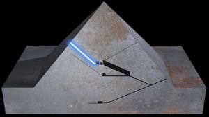
To find the position and the related measurements of all numbered blocks,
see the CHEOPS SHAFTS
drawing
at the CYBER DRAWINGS
page.
All
copyrights Rudolf Gantenbrink 1999
Like all the other wall stones of the King's Chamber, Block No. 1 is granite. At this inlet point, the shaft is made up of three blocks. Early treasure hunters dug a round tunnel into the block above the shaft itself (compare Maragiolio and Rinaldi, "L'Architettura della Pyramide Menfite", Parte IV).
This initial horizontal shaft segment is 1.72 meters long. At the beginning of Block No. 2 the shaft inclines at an angle of 39.20° (manually measured). This segment of the shaft is nearly round in cross-section and seems to have been enlarged after its initial construction, probably by the same treasure hunters mentioned above.
At Block No. 3 the shaft inclines more sharply, reaching an angle of 50.54° (manually measured), which it maintains to the end of Block No. 4.
Block No. 5 is not accessible to conventional measuring procedures. Here, our video images show that the shaft's angle of ascent declines. From this point, all the way to the outlet on the pyramid's flank (we measured both points), the shaft maintains an angle of 45°. So, despite the extreme fluctuations in the initial section, the shaft seem to proceed with great exactitude and constancy.
From Block No.
12 onwards, Upuaut-1 detected sunlight, which until that point was blocked from view by a bend in the longitudinal axis. We were able to use the tiny dot of sunlight on the "horizon" ahead of the robot to evaluate very precisely the video material. This even allowed us to determine the amount of longitudinal bend in the shaft.
(See BENDS 3D at the CYBER DRAWINGS page)
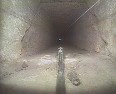
The far end of Block No. 5 is unfinished. As a result, the height of the shaft drops to only 9 to 10 centimeters.

The unfinished ceiling of block No. 5. Note Upuaut's towing cable
along the upper right, 8 cm above the floor.
This is an obvious example of inferior workmanship, what we refer to as a "Monday morning block." Block No. 5 was almost certainly inserted without authorization from the architect or master builder. The discovery of a number of such unfinished blocks in both upper shafts and in the lower southern shaft well would seem to indicate that the "shaft builders" made up a separate working group. This group apparently lagged behind at times, pressured by the rapid rate of growth of the pyramid layers and the construction of the chambers. This would also explain the extreme angle fluctuations in the vicinity of the King's Chamber.
Between Block No. 15 and 16 we discovered a vertical joint. In the shafts such joints, which have a distinct static function, otherwise occur only proximate to the chambers. (For more information on the normal arrangement of joints, see GENERAL REMARKS at THE FINDINGS page.)
It is a complete anomaly to find a vertical joint fully isolated in the nucleus of the pyramid. Since it requires much greater effort to shape and fit the blocks in such an arrangement, we can assume that the builders must have had significant structural justification for going to the trouble of deflecting forces into the horizontal plane.
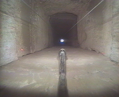
The unusual vertical joint.
(In the center of the image you see the dusty laser rod of UPUAUT-1)
This vertical joint is located about 12 meters above a point in the LOWER SOUTHERN SHAFT which is subject to extraordinary static influences (see LOWER SOUTHERN SHAFT , BLOCK No. 25).
The overall static's in this area seem to differ from those in the other shaft segments. For a construction engineer this is a significant clue to the possible existence of an as yet undiscovered structure in the vicinity of these static anomalies.
At the end of Block No. 17 the shaft bends slightly to the east (see BENDS 3D at the CYBER DRAWINGS page). We were able to determine this during the video evaluation, on the basis of Upuaut-1's tow line, which ran parallel to the shaft.
In both shaft walls at the end of Block No. 23, we discovered an arrangement of niches (see CHEOPS NICHES at the CYBER DRAWINGS page), whose function remains unknown.
The niches on the left and right walls of the shaft. The two laser dots
are beamed on the recesses of the niches.
Prof. Stadelmann suggested (see MDAIK 50 / 1994) that this might constitute a parallel to the "closure stone", i.e., the "slab", in the lower southern shaft. He meant that the niches could have formed part of a former mounting structure for a shaft closure stone. At first glance, this hypothesis would seem to make sense. But closer examination of the data we collected makes it highly questionable.
1. The eastern niche forms a groove; the western niche a recess, extending to the end of the block. So a small plugging stone of the kind envisaged by Prof. Stadelmann would be held in place on only one side. The groove on the eastern side would serve no purpose.
2. A small plugging stone could not have been lowered into the shaft from above, as Prof. Stadelmann suggested, because the shaft in block No. 23 is wider than block No. 24. (In 1992, Upuaut-1 made laser measurements of all relevant widths and heights in both upper shafts.) Thus, a plugging stone narrow enough to fit the dimensions at the top of the shaft would simply slip past the niches. (See CHEOPS NICHES at the CYBER DRAWINGS page for details.)
3. Prof. Stadelmann's hypothesis allows for the possibility that the plugging stone was embedded in place during construction of the shaft itself. He doesn't explain, however, how this stone, embedded 12 meters deep into a shaft measuring only about 20 x 20 centimeters, was later removed without doing even the slightest damage to the niches.
4. Even if we choose to assume that the groove and the recess originally held a stone slab, we still face the problems mentioned above. Any such slab would have to have been inserted before the corresponding block was set in place, and thus could not have been removed later without damaging the niches.
The vague possibility remains, of course, that a stone slab was planned at this spot, but never actually built into the construction. Even this case, however, does not constitute an exact parallel to the situation in the lower shaft, because the upper shaft ceiling has no recess like that in the lower southern shaft at the slab. (See LOWER SOUTHERN SHAFT block No.28).
The upper butt joint of Block No. 23 is also unusual, in that it forms a rectangular concave profile. (See CHEOPS NICHES at the CYBER DRAWINGS page). It is also remarkable that here the floor joint is aligned with the shaft joints.
After the last remaining original block, No. 25, the shaft extends another 1.70 meters, restored in the more recent past, before it outlets on the flank of the pyramid.
THE UPPER NORTHERN SHAFT THE LOWER NORTHERN SHAFT THE LOWER SOUTHERN SHAFT
|

 CULTURE BY TABAC