GENERAL
REMARKS
With a few minor
exceptions, the four so-called "air shafts" of the Cheops Pyramid were
constructed in accordance with one unvarying system. The shaft roof and
both walls were cut from one block to form something like a stone canal.
The floor was provided by a second block, effectively sealing the shaft
from below. Thus, the joins connecting the upper blocks normally ran perpendicular
to the floor of the shaft.
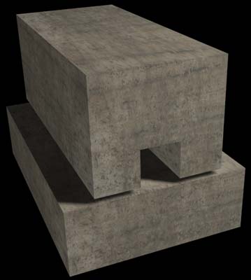
Typical
shaft and floor block.
Each of these sets
of two blocks had to be fit into the horizontal layers of the pyramid using
wedge-shaped blocks. Thus, each shaft sequence required the special fabrication
of four blocks. As we observed in the Caviglia Tunnel, in the "Mankiller"
Tunnel (see SECOND
1992 CAMPAIGN at THE
UPUAUT STORY page), and at the
outlet of the upper southern shaft, the overall static structure relevant
to the shafts measures approx. 2 X 4 meters.
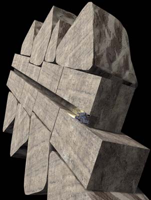
Cross-section
of the shaft showing the statically relevant structure.
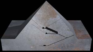
This construction
system gave rise to a continuous diagonal joint, at the floor of each shaft,
running through almost half of the pyramid. Considered statically, such
continuous joints are extremely dangerous. They can be regarded as something
like a sliding board. The sliding of great mass along such continuous joints
would necessarily lead to the collapse of the chambers. The ancient builders
were obviously aware of this problem. In the "Mankiller" Tunnel, for example,
we found a so-called "griddle stone". Thus, the pyramid builders obviously
went to great effort to deflect the sliding forces, a measure which speaks
for their highly advanced understanding of static processes.
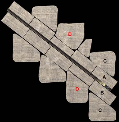
A =
shaft blocks B = floor blocks C = wedge-shaped
blocks D = griddle stones
Using the robot Upuaut-1,
we were able to measure exactly the width and height of the two upper shafts
along their entire lengths. Normally, the shaft width never varies by more
than 5 millimeters, but the shaft height fluctuates by up to 2 centimeters
(with the exception of uncompleted shaft sections). On average, the shafts
measure 20.5 centimeters in width and 21.5 centimeters in height.
But in the vicinity
of the chambers and the sharply-angled shaft segments, the fluctuations
are larger. Here, shaft width varies between 17 and 22 centimeters, shaft
height between 14 and 23.5 centimeters.
As we verified in
1992, the upper southern shaft emerges on the exterior at the 101st layer,
the upper northern shaft at the 102nd layer. In this regard, Maragiolio
and Rinaldi report incorrect values. (see Maragiolio and Rinaldi, "L'Architettura
delle Pyramidi Menfite, Parte IV).
The shaft blocks
were probably made, for the most part, from local limestone. This supposition
is supported by the numerous imperfections we detected in the blocks.
BACK
TO THE LIST
ADDITIONAL
MEASUREMENTS
SHAFT
INLETS WITHIN THE CHAMBERS
Distance between
the east wall of the chambers and the east wall of the shafts.
Kings Chamber Southern
Shaft 2.49 m /
Shaft width 18 cm Shaft height 14 cm
Kings Chamber Northern
Shaft 2.48 m /
Shaft width 21 cm Shaft height 14 cm
Queens Chamber Southern
Shaft 2.88 m* / Shaft width
21 cm Shaft height 21 cm (Opened
by Dixon)
Queens Chamber Northern
Shaft 2.90 m / Shaft width
21 cm Shaft height 21 cm (Partly
opened by Dixon.)
With
the exception of this one*, all values reported by Maragiolio and Rinaldi
are incorrect.
(See
Maragiolio and Rinaldi, "L'Architettura delle Pyramidi Menfite, Parte IV.)
SHAFT
OUTLETS ON THE PRESENT PYRAMID FACE (excluding the missing
casing.)
Height above the
original base paving of the pyramid.
Kings Chamber Southern
Shaft 77.55 m
Kings Chamber Northern
Shaft 78.43 m
Shift from the central
North-South axis to the eastern wall of the shaft.
Kings Chamber Southern
Shaft 5.20 m East
Kings Chamber Northern
Shaft 1.57 m East
Please
note: on Maragiolio and Rinaldi's drawings the central axis is shown 7.20
m east of the corridor / chamber system . In reality it lies 6.82 m west
of the system, measured from the center of the corridors.
(See
Maragiolio and Rinaldi, "L'Architettura delle Pyramidi Menfite, Parte IV.)
The
distance between the central North-South axis and the eastern Chamber walls
is 7.84 m.
BACK
TO THE LIST
|